What Does a Steering Wheel do?
You realize that when you turn the steering wheel in your auto, the wheels turn this is definitely a case of cause and effect If this is the case, a considerable measure of fascinating stuff goes ahead between the steering wheel tires to get this going, and this is phenomena is what this guide seeks to break down for you.In this article, we’ll perceive how the most widely recognized kinds of car directing frameworks work. The controlling framework changes over the pivot of the guiding wheel into a swiveling development of the street wheels so that the directing wheel edge turns far to move the street wheels a short way.
Steering Wheel Mechanism
Simple Tips on Steering Wheel Mechanisms
Most recent cars utilize a steering system known as a rack-and-pinion steering; if the term doesn’t sound familiar, this article will serve to edify you on the function of a steering wheel.

Photo on driving-tests.org
Steering System Parts List 1: Steering Wheel
More often than not a steering wheel is situated before the seat of the driver and it functions to control the direction in which the wheels move while giving the response on the status of the wheels. There are various types of steering wheels you can choose from, and you’ll also find that they have buttons that control other car functionalities like the sound system, car seats etc.
Steering System Parts List 2: Shaft
This part of the steering system is majorly known as a steering shaft which sticks out into a wall of your auto. Let’s say you’re caught up in an accident, most of the recent cars have the ability of a cave-in steering shaft that helps the driver avoid the severity of injuries.
Steering System Parts List 3: Rotary Valve
- Now, an auto with pressure driven power steering has the guiding shaft run straightforwardly into a rotating valve.
- A revolving valve opens and closes as it is pivoted to permit pressurized hydromechanical liquid to help the steering shaft in turning the two meshed gears, popularly known as the pinion gear.
- As a result, steering your auto becomes substantially less demanding, particularly when driving at low speeds and when halted.
Two Main Types of Steering System
Hydromechanical aka Hydraulic Power Steering System
- This type of steering uses a pressure driven cylinder fueled by a belt linked with the auto’s motor.
- The pump pressurizes the water-driven liquid, and the water-powered lines keep running from the pump to the revolving valve at the base of the directing shaft.
- Numerous drivers lean toward this sort of intensity directing, both for its reasonableness and for the criticism of street feel to the driver.
- Thus, most sports automobiles have utilized pressure fluid-driven power guiding or no power directing at all for a considerable length of time.
- As of late, however, headways with electric power directing have introduced another time of games autos with electric power guiding.
- In situations where an auto, has an electric engine along the guiding shaft, at that point, the automobile is furnished with electric power steering.
- This framework permits greater adaptability with where the electric engine can be mounted, making it ideal for retrofitting more established autos.
- This framework additionally does not require a water driven pump to work.
Electric Power Steering System
- Electric power guiding uses an electric engine to help with turning either the controlling shaft or the pinion outfit straightforwardly.
- A sensor along the controlling shaft detects the level at which the driver pivots the directing wheel and will now and again likewise sense how much power was utilized to turn the guiding wheel (known as speed affectability).
- The computerized system of your car at that point forms this information and applies the proper measure of power with the electric engine to help the driver with directing in a split second.
- While this framework is cleaner and lower-upkeep than a pressure driven structure, numerous drivers say electric power controlling feels excessively detached from the street and may help overly in multiple applications.
- Electric power guiding frameworks are enhancing with each model year, however, so this notoriety is evolving. In situations where there is nothing toward the finish of the controlling shaft except for the pinion adapt, at that point, the auto does not have control directing.
- The rounded gear (pinion) item sits on the controlling rack.
Photo on shopify.com
Steering System Parts List 4: Steering Rack
- The controlling rack is a long metal bar that runs parallel with the front pivot. Teeth in a straight line along the highest point of the rack adjust splendidly with teeth on the pinion adapt.
- The rounded gear pivots and moves the directing rack on a flat plane to one side and directly between the front wheels.
- This gets together is in charge of making the rotational vitality from the controlling wheel into left-and-right movement valuable for moving two wheels in parallel.
- The measure of the pinion adapt in respect to the controlling rack chooses what number of turns of the directing wheel it takes to turn the vehicle a specific sum.
- A littler apparatus implies more straightforward turning of the wheel. However, more revolutions to get the wheels turned the distance.
- At the two finishes of the guiding rack sit tie poles.
Steering System Parts List 5: Tie Rods
- Tie poles are long thin connective pieces intended to be extremely solid just when pushed on or pulled. Power from another edge could go without much of a stretch twist the pole.
- The attach poles link with the directing knuckle on either side, and the guiding knuckles control the wheels turning left and right pair.
- Something to remember with the guiding framework is that it isn’t the central framework in the vehicle that needs to move unequivocally while at speed.
- The suspension framework likewise does a lot of moving, implying that a turning auto going over an uneven surface would do well to have a route for the front wheels to move side-to-side and here and there all the while.
- Swiveling junctions come in at this point; this is a joint that resembles a ball-and-attachment joint on a human skeleton.
- This part takes into consideration the free development that the plain unique guiding and suspension frameworks need to work hand in hand.
Photo on squarespace.com
Steering Wheel Parts
- For more up to date autos, with rack and pinion directing, there are two primary power guiding parts, the pump, the rack, and rounded gear unit and hoses.
- Recorded beneath are the majority of the elements in an advanced power controlling framework, and the capacities they serve.
General System Function
- In a propelled coordinating control system, the pump gives control directing fluid under strain to the rack and pinion unit.
- Exactly when the driver gives managing commitment by turning the coordinating wheel, the power controlling control valve applies fluid weight to the opposite side of a barrel, which helps the driver in turning the wheel. When you’re driving, immediately you turn the wheel, the pinion deceives the rack, and both being gears, this pushes the rack the desired way, which turns the wheels.
Power Steering Pump
The power managing pump is turned by the adornment drive belt or serpentine belt to make fluid weight in the high side power controlling hose to the data side of the power coordinating control valve.
Rack and the Round gear (aka Pinion)
- The rack and the round gear (pinion) is the unit which enables the driver to manage the improvement of the front wheels for turning.
- There’s a rounded gear furnish which links with the completion of the controlling data shaft
- This gear is pressed against the controlling rack.
- As the controlling wheel turns, the pinion rotates and pushes the rack toward the way needed.
- On either end of the controlling rack are elastic treated plastic thunders, which secure to the rack body and the moving bit of the rack to shield dust from entering the rack and pinion unit.
Directing Yoke
- Between the rack and round gear (pinion), inlet chamber and the coordinating segment is the managing damper.
- This is a thick flexible piece which acclimatizes road dazes and shields them from being traded to the driver through the directing wheel.
Tie Rod Ends
- These are parts that join the terminations of the controlling rack to the managing knuckle and empower the development of the rack to be changed over into turning advancement of the front wheels.
- These parts turn on a level plane for directing data translation and pivot vertically and moreover corner to corner when the vehicle encounters disagreeableness in the road, and the wheels ricochet.
Power Steering Hoses
- There are two essential power coordinating hoses, the high side, and the low side.
- They’re both linked with the rack and pinion with hung metal fittings.
- The high side hose joins the power controlling pump with a hung metal fitting, while the low side hose slides over a little pipe and is tied down with a hose cut.
- The high side hose passes on control managing fluid under strain to the rack to give the power help to controlling information sources.
- The low side hose passes on low weight fluid back to the pump.
Types of Car Steering Wheel
2 Main Types of Car Steering Wheel
Photo on skoda-uae.com
Rack and Pinion and Recirculating Ball Steering are the two most conventional system utilized to date.
Rack and Pinion (rounded gear)
Rack-and-pinion controlling is the most broadly perceived kind of development control instrument in automobiles, little trucks, and SUVs.
Design – A Rack and Pinion adjust set is encased in a metal tube with each completion of the rack pointing out from the tube. A post – tie shaft or essential bar – partners with each completion of the rack. What happens next is the adding of the pinion adjust to the coordinating shaft. How it Functions
- When you turn the controlling wheel, the device will turn, moving the rack. The connect bar interfaces with the coordinating arm, which is added to a hub.
- The purpose behind a Rack and Pinion adjust to change over round development of the coordinating wheel into the straight progress.
- Making it less requesting to turn the wheels.
- The two sorts of rack-and-pinion coordinating structures:
1. End take-off 2. Center take-off
Variable Ratio Steering
A subtype of Rack and Pinion adjust coordinating is Variable Ratio Steering. This coordinating structure has differing number of tooth pitch at within than it has at the terminations. Variable Ratio Steering makes the controlling less fragile when the coordinating wheel is close to its center position. Additionally, turning it towards jolt, make the wheels more unstable to round development of the steering wheel.
Re-coursing Ball/Steering Box
Re-coursing Ball Steering is the most, for the most part, used steering structure in overpowering autos. It continues running on Parallelogram linkage, in which:
- The Pitman and Idler arm remain parallel
- The framework ingests overpowering stagger weights and vibrations
Design – The coordinating wheel rests onto the controlling shaft, which has a hung post toward the end. The hanging shaft is settled, not in any way like in the Rack and Pinion make. The strings in the bar are stacked up with metal rollers. These metal balls have two limits: To diminish rubbing and wear in gear; Fixing the teeth of the mechanical assembly to keep the past from breaking contact with each other when the controlling wheel changes course. Basic Functioning – The shaft turns just immediately after the wheel starts to rotate. Right when the wheel turns, the square moves. The square moves another mechanical assembly that in this way shifts the Pitman’s arm. The metal rollers in the strings re-course through the mechanical assembly as it turns.
How do you Hold the Steering Wheel While Driving?
Proper Techniques of Holding the Steering Wheel
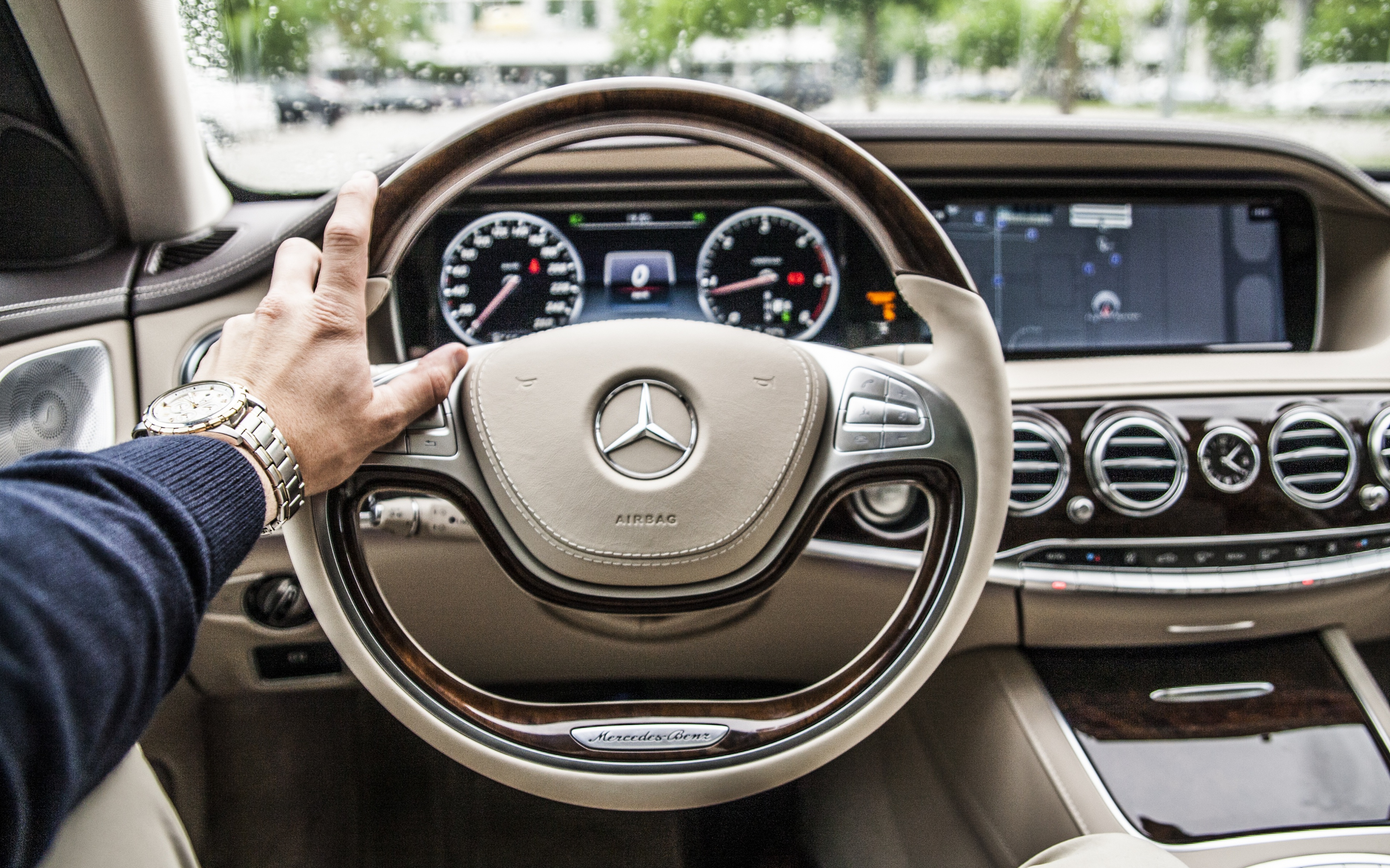
Photo on wallpapersbyte.com
Holding the steering wheel of your vehicle in the right manner is a critical step to watch each time you get in the driver’s seat. Drivers who utilize the right strategy to hold the wheel of their vehicle generally use their cars more effectively and also have fewer chances of being involved in an accident.
Don’ts on Holding a Steering Wheel
As a rule, you don’t need your hands in a position where your lower arm crosses the focal point of the wheel. This technique incorporates on top of the wheel or over to the alternating side. Not exclusively do you have far less control in a crisis? Not exclusively do you have far fewer control in a crisis?Disregard the “10 and 2” holding technique because it may lead to unprecedented injuries.
“10 and 2” Steering Wheel Holding Technique
Back before airbags, it was adequate to clutch the controlling according to the educator’s “hands at 10 and 2” order still impacts the manner in which you get a handle on the directing wheel. It remains a prominent confusion; however, there’s a more secure approach to grasp the wheel.
“9 and 3 ” Steering Wheel Holding Technique
The suggested position of your hands is currently at 9 and 3 o’clock, with the thumbs set along the edge instead of circling it. In case of a mishap, the power of airbag organization can send hands at the highest point of the wheel into your head or even break thumbs. An airbag conveys at around 200 mph, and there’s just no chance you can move your hands sufficiently brisk to beat that, so hold the guiding wheel at 9-3 and keep away from the hazard. Four-wheel drivers think about this, however not due to airbag arrangement reasons. Let’s assume you’re driving through rough terrain and hit a stone and the directing wheel yanks to the other side. If your thumb bolts around the steering wheel edge the torque could break your thumbs or disjoin them.While we’re regarding the matter, never lay your hand on the center point of the wheel or utilize an underhand grasp while turning—it’s an excellent method to wind up with a broken arm in a mishap.
“8 and 4” Steering Wheel Holding Technique
The once favored “10 and 2” technique has changed as of late to eight and four, where allowed by the wheel spokes. Studies have demonstrated that keeping the hands marginally lower, underneath the level of the heart, results in enhanced blood flow to the hands and less probability of “tingly” fingers.
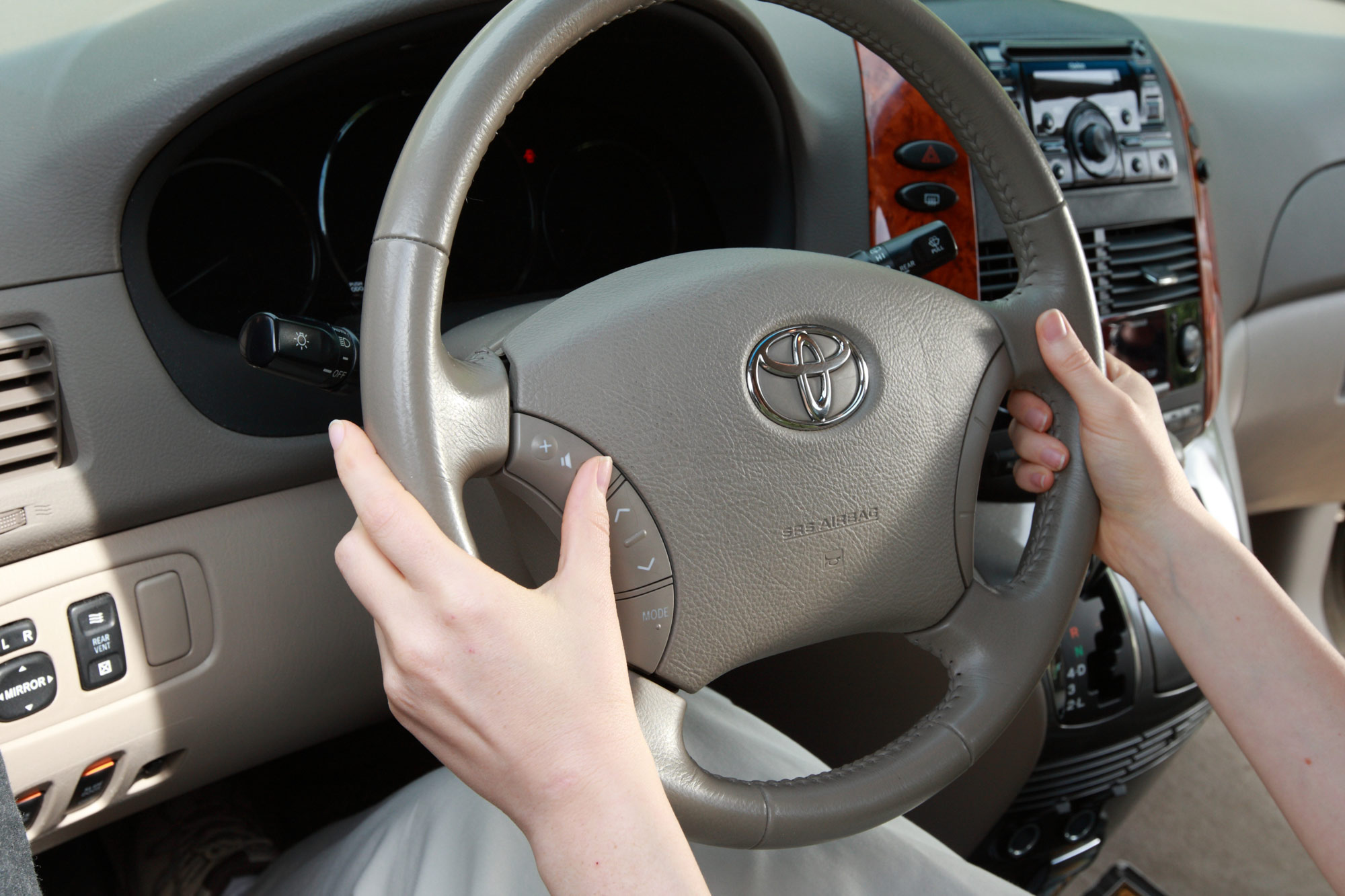
Photo on crutchfieldonline.com
Essential Tips For Holding Proper a Steering Wheel
As a driver, your first concern should be ensuring you are well seated in your car seat; and you’re feeling comfortable; no one wants an uncomfy and grumpy driver behind the wheel. Depending on how big or small you are, you may need to adjust the wheel, and you can easily do this through a lever located either on the side or beneath the steering wheel; it enables the steering wheel to move either up or down accordingly. An alternative is to either pull your car seat closer or further behind depending on how comfortable you feel. Ensure you can use all the mirrors in your vehicle; the rear view mirror, your side mirror, and the passenger side mirror. Let’s use a hypothetical clock, place your left hand on the left segment of the controlling wheel in an area close to where the nine would. Place your other hand on the right part of the wheel where the three is on the clock.The “9 and 3” technique helps you turn the vehicle with ease through the push and pull method. Instead of taking your hands off the steering wheel as you make a turn, utilize the push and pull method to ensure safety and also to prevent your hands from getting sore.